
- Details
- Category: Setup
The IDE card was designed by Thierry Nouspikel in 2001, later revised in 2004. The card does not have any ROM on board, so there are no ROM zip files to get the card going. However, there is a process of installation where the DSR is written on the IDE drive and a mini loader program (bootstrapper) is included to load the DSR from the drive at system startup.
Overview
The original concept from Th. Nouspikel included to load this bootstrapper into the battery-buffered real-time clock on the card (when using the RTC-65271). Other card revisions allowed for the use of BQ chips (like BQ4847, BQ4842, and BQ4852), some of them shipped with internal non-volatile SRAM or provisions to connect external SRAM.
Th. Nouspikel designed the DSR to provide a collection of floppy disk emulations. That is, by means of certain peripheral commands, the floppy image can be swapped for another one.
Fred Kaal redesigned the DSR completely to offer real hard drive access as devices "IDE1" to "IDE8", one for each partition. This allows the user to make use of up to 8 · 248 MiB of capacity. The hard drive partitions comply with the usual TI DSR conventions, in particular the HFDC and SCSI, so that nested subdirectories are possible. The maximum capacity for a partition cannot exceed 248 MiB because of the 31 sector long allocation table that can manage at most 63488 allocation units (clusters) with a maximum of 16 sectors of 256 bytes (see the description of the file system on Ninerpedia).
I recommend to use Fred's DSR, and this will also be the base for all following explanations.
The IDE support consists of two parts:
- the emulated IDE card with its DSR in the nvram subdirectory
- one or two emulated IDE hard disk drives and their respective image files
In order to set up the IDE support, we will at first prepare the IDE card, in particular including the upload of the DSR into the NVRAM. Then we will have to prepare a hard disk image to be mounted in the IDE drive.
Setting up the card and its DSR
At first we should take care that the loaded NVRAM will not get lost when you change the configuration. Therefore, I suggest to use a special nvram directory and also a special configuration directory for IDE use. We can set these directories in the command line, overriding the defaults in the mame.ini file. If you use a script (batch) file for launching your MAME emulation, this is the ideal way to set these paths:
mame ti99_4a -cfg_directory cfgide -nvram_directory nvramide -ioport peb -ioport:peb:slot2 32kmem -ioport:peb:slot7 ide -ioport:peb:slot7:ide:ata:0 hdd
The IDE card has some DIP switch settings. You find these settings in the OSD menü ("DIP switches"). Enter this submenu and verify that these settings are active:
CRU base: 1900Map at boot time: SRAMCard mode: TI
Also, we have to check whether the correct RTC chip is selected on the emulated card. In the OSD menu, select "Machine configuration":
Genmod decoding:   off
RTC chip:          BQ4847 (ext SRAM)
The BQ4847 is a good choice. Do not use the RTC-65271; it will not work with Fred's DSR, it is only useful for Thierry Nouspikel's original DSR. The Genmod decoding should remain off, unless you are configuring for the Genmod.
Now let us test whether the DSR must be installed at all. Maybe this was already done earlier, and we just forgot about it. Enter TI BASIC and try this:
 TI BASIC READY
> CALL IDEST
 * BAD NAME
If you get this error message (bad name), the DSR is not installed.
Installing the DSR
Fred Kaal offers the DSR on his website. Click on "Projects", and then on "Ide Dsr" on the right side (deep link). Download the file by clicking on the archive symbol at the top of the page ("Download the IDE DSR program as a ZIP file"). You should find a file "idedsr_vXX.zip" (with XX=16 or later) in your Downloads folder. Inside the ZIP archive there is a file "IDEDSRXX.dsk". Store this file in your floppy disks folder or anywhere where you can reach it easily.
Now run your emulation with the disk in the floppy drive and with the Editor/Assembler cartridge:
mame ti99_4a <options from above> -cart editass -flop1 IDEDSR16.dsk
You should store the command line in a script file for later use. Enter Editor/Assembler, select option 5:
* RUN PROGRAM FILE *
FILE NAME?DSK1.IDELOAD
The program should now load. When it starts, it should show:
**** IDE-DSR VXX loader (xx/xx/20xx) ****No configured IDE device found
Select: 1 for DSK1. ...
Press 1 for DSK1. In the following screen, set the CRU address to 1900 (just type 9), unless you set another address above. The program tries to detect the clock chip automatically. Sometimes this may fail, and then it assumes the BQ4847 (hence, a good choice). It then loads all DSR files and uploads them to the NVRAM. When done, you are returned to the initial menu, and you should now see
IDE device found @ CRU >1900with RTC type BQ4847 (not set)
You can set the IDE clock with option 7, but this is not necessary, as the clock chip is automatically synchronized with the PC clock where you run MAME. When all is done, press FCTN-9 to leave the program, and enter TI BASIC to verify that the DSR was properly loaded. For that purpose, enter the CALL IDEST command as shown above. You should now see the version of the IDEDSR, and a list of IDE1...IDE8 status lines. If you do not already have a formatted hard disk image, you will see all zeros here.
Create a hard disk image
We will do this "the hard way" first. Actually, most of the following can be done more easily with TIImageTool's help.
Create the plain HD image
First we have to create a hard disk image file. Use the chdman command from MAME. We will go for one 100 MiB drive that we want to have three partitions.
chdman createhd -o mynewide.hd -s 104857600 -ss 512
This should create a new file "mynewide.hd", size is 100 MiB, and the sector size is 512 bytes. Note that IDE drives always use sector sizes of 512 bytes, not 256. The DSR, however, translates this to 256-byte TI sectors.
Partition and format the HD image
Check that this file has been created. Now you need Fred's DU2K program to partition and format the hard drive (deep link). Download the ZIP archive and put the files DU2K, DU2L, and DU2M on a floppy disk image (e.g. with TIImageTool).
Here is a ready-to-use disk image (also including the files of the DSR v1.6): idedsr16_du.dsk. Run MAME with both the floppy and IDE image mounted, like this:
mame ti99_4a <options from above> -cart editass -flop1 idedsr16_du.dsk -hard1 mynewide.hd
In Editor/Assembler, run DU2K with option 5.
* RUN PROGRAM FILE *
FILE NAME?DSK1.DU2K
You should see the entry screen of DU2K. First thing is to check whether the IDE hard disk is accessible.
- Press 1 to display the available devices, the 1 for IDE. You should see "IDE1 [MAME Compressed]" and no further devices.
- Press 2 to create the partition table. Select [M]aster, then [C]hange.
- Our hard disk has 0x32000 sectors. We will set up three partitions of similar capacities. Press Return each time to complete the input. Use Alt-S (FCTN-S) to step left.
- Select partition 1, enter size 10000.
- Select partition 2, enter size 10000.
- Select partition 3, enter size 11FFF.
- Do not forget to [S]ave.
- Go back (FCTN-9), select 4 for Initialize.
- Since the three partitions are accessible as IDE1, IDE2, and IDE3, repeat the initialization for each of them. Give your partitions meaningful names.
Leave DU2K by entering Q in the main menu.
Testing
Let's do a quick test. Go into TI BASIC and enter a short BASIC program.
10 PRINT "HELLO WORLD"20 END
Save it to your new IDE harddisk.
SAVE IDE1.HELLO
Try to load it. Enter NEW (or restart the emulation) and type
OLD IDE1.HELLO
If it loaded, welcome to the world of IDE hard drives!
Be faster with TIImageTool
As I said above, you can avoid all the detail work with DU2K if you create the IDE image in TIImageTool.
Open the File menu, choose "New partitioned IDE image". There you can create all desired partitions. Save it as CHD Image, e.g. as "timtide.hd".
As above, close TIImageTool, mount the IDE image file as shown above
mame ti99_4a <options from above> -hard1 timtide.hd
Type in a short BASIC program, save it as IDE1.TEST (or IDE2 if you want to save it on the second partition), and try to load it again.
- Details
- Category: Setup
Preparing the build environment
This should be required only once. We will use a GNU environment in Windows for building. You can also try Visual Studio, but since I do not have it, I cannot give further help here. See https://docs.mamedev.org/initialsetup/compilingmame.html for further information.
Most of the following information can be found on the MAME Documentation Wiki: Compiling MAME in Windows
1. Download MSYS2 and install it
For Windows x64, please download the installer from the MSYS2 website. This is free software.
Start the executable package by double-click. The installer allows you to choose an installation directory; if you do not pick the default (C:\msys64), make a note of it and replace the default path whenever it appears in the following setup. You can run MSYS2 Setup directly from the installer.
Should Windows Defender warn you about a possible security hazard, please ignore that and insist on installing (More info, Install anyway).
2. Set up MSYS2
When you run the setup, you should see something similar to the Windows command prompt, but with colored text, and a cursor blinking after a $ sign. This is the Unix-like build environment that we will use. In the following text, the commands you have to type in are shown in blue after the $ sign (which you do not type). Please make sure you type these command exactly as shown, including uppercase or lowercase. You can also copy the text and paste it behind the $ sign.
Whenever you are asked whether to proceed with the installation, enter Y or hit Return.
$ pacman -Syu
This updates the current installation.
$ pacman -S git make unzip
Installs the git, make, and unzip commands. Git is used to manage the source code, for example, allowing you to download the latest changes.
$ pacman -S mingw-w64-x86_64-gcc mingw-w64-x86_64-libc++ mingw-w64-x86_64-python
Installs the compiler, libraries, and the Python interpreter.
$ cd ~$ curl -O "https://repo.mamedev.org/x86_64/mame-essentials-1.0.6-1-x86_64.pkg.tar.xz"$ pacman -U mame-essentials-1.0.6-1-x86_64.pkg.tar.xz$ echo -e '\n[mame]\nInclude = /etc/pacman.d/mirrorlist.mame\nSigLevel = Never' >> /etc/pacman.conf$ pacman -Syu$ echo "export MINGW64=/mingw64 MINGW32=" >> .bashrc$ exit
These are some final settings before building MAME.
Get the sources
Open the command window again (search for MINGW64 in the Start menu), type the following:
$ git clone https://github.com/mamedev/mame.git
This will download all MAME sources from Github. This may take some minutes; the source tree contains nearly 30000 files. You should see a new "mame" directory in the folder.
3. Compile MAME
If you are not already in the mame directory, enter it with the cd command.
$ cd mame$ make -j4 SOURCES=ti/ti99_4x.cpp,ti/ti99_4p.cpp,ti/ti99_8.cpp,ti/geneve.cpp,ti/ti99_2.cpp REGENIE=1
If your PC has sufficient CPUs/cores, you can choose a higher job count (for example, -j12). You should copy this line in a file and store it in the mame folder (like "maketi"). You can then start compilation with
$ ./maketi
After compiling has finished, you should have a freshly built mame executable file. Copy this file into your MAME working directory.
4. Update MAME
$ git pull$ make clean
With pull, your local installation is updated with all changes on Github. You should do a make clean, as shown, to avoid trouble during compiling. Then continue as described below "Compile MAME". For more information about git, please check the online documentation.
5. Forget about steps 2-4 and use my tools
I prepared some small scripts to make the preparation, building, and installation easier. You can, of course, adapt these files to your personal needs.
- prepare: Set up MSYS2 as described above.
- clean: Clean the build directory from a previous build
- maketi: Build MAME.
- mameinst: Install the newly built MAME in the target directory
- mameprep_msys2: Fetch all ROMs and create suitable starter batch files.
This will lead you quickly through the installation and configuration process:
Download MSYS2 and install it
As described above, download the executable package and start it. Run MSYS2 from the installer as proposed at the end.
Download the prepare script
Put the prepare script in your home directory. This is the directory where you find yourself when opening MSYS2. Typically, it should be C:\msys64\home\yourname. The other three scripts are automatically retrieved.
Configure MSYS2
Run the prepare script in your home directory. Watch the output. Ideally, it should do everything mentioned above in tasks 1 and 2.
Build MAME
Run the maketi script in the mamegit subdirectory that has been created by the prepare script.
Install MAME
Run the mameinst script in the mamegit subdirectory that has been created by the prepare script. MAME will be installed in the directory C:\prg\mame.
Get all ROMs
On the first installation, the mameinst script will remind you to fetch the necessary ROMs. Go into the target installation directory (by default /c/prg/mame) and run the mameprep_msys2 script. When it is done, you will find a new folder on your desktop, containing batch files to run various TI and Geneve systems. This is done only once.
6. Troubleshooting
Sometimes, things don't work as expected, even though you swear that you did everything as you were told.
Python not found
When you start building MAME, you get the message after some time that Python was not found.
Check: Did you install Python as described above? In the command shell, enter this:
$ /mingw64/bin/python
Does this work? That is, do you get a "No such file or directory" error, or is there a Python command prompt (">>>") ? If so, exit Python with quit(). Obviously, Python is not in your path.
Check exactly what prompt you see: Is there a MINGW64 or MSYS? If you see MSYS, you opened the wrong command window. Close it and search for "MINGW64" in the Windows start menu. You might want to create a shortcut on your desktop.
Scripts are not found
Although you verified that you are in the correct directory, you see this:
$ maketi
-bash: maketi: command not found
Note that in Unix systems, the current directory is not contained in the command search path. To execute a file outside of the search path, you must provide the directory in which it is located. This is done easily by using the period as the current directory:
$ ./maketi
And now you notice that I actually wrote that in the explanation above.
- Details
- Category: Setup
The TI-99/4A emulation offers two kinds of cartridge formats:
- the common ZIP format for ROM packages in MAME
- the RPK format
The first format is used throughout MAME for bundling ROM dumps that belong to some collection, for example, all ROMs for a computer system. In the same way, all ROMs of a cartridge are stored in a single ZIP file, which must be added to the software list, a XML file in the hash subdirectory. For the TI, this would be the file ti99_cart.xml.
The second format was the result of an earlier attempt to find a format for cartridges. Later, the ZIP format became the recommended format for cartridges, but it has a shortcoming: It depends on an update of the mentioned XML file. The RPK format, on the other hand, allows the user to set up a self-contained cartridge package that can be used right away. For this reason, the RPK format was kept in MAME.
Basic concept of a MAME cartridge
A cartridge consists of a printed circuit board (PCB) and some memory circuits mounted on it. A few cartridges may also have additional features like switches, but these are currently not emulated.
In order to emulate the cartridge, we need the contents of the memory circuits and the type of the PCB. Although the PCB may theoretically contain any kind of circuitry, there are only about a dozen different types. All these PCBs are already emulated inside MAME, so we just need to declare which one to choose by name. We have to point out that if a PCB has a different design, this cannot be used in MAME until it is implemented and added to the emulation.
The contents of the memory circuits must be provided by up to three dump files:
GROM dump
The GROM dump spans the whole GROM cartridge space, which reaches from G>6000 to G>FFFF (40 KiB). Each real GROM offers 6 KiB of memory; the remaining 2 KiB are not usable (combination of other contents, see the entry on Ninerpedia). The dump, however, must also contain these unusable bytes so that all good locations properly line up in memory, except for the last part. As you see below, this dump contains GROM3 to GROM5. All bytes after G>B7FF are filled with 00.
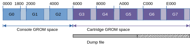
The TI-99/4A console does support multiple banks of GROMs, but they are not used in cartridges. Expansion cards like the HSGPL actually support these banks, but they use a different way of storing the cartridge contents.
The dump file is traditionally named like XXXXg.bin, where XXXX is the cartridge name and "g" indicates a GROM dump. This naming is not required in MAME's RPK format because the meaning of the dump file is defined in the layout.xml file. However, to ensure compatibility with other emulators, this naming scheme is still recommended.
ROM dump
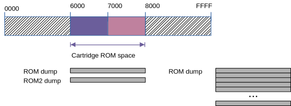
The cartridge ROM space is located at addresses >6000 through >7FFF. A ROM dump contains these bytes; if fewer are stored, the remaining space is filled with 00.
Classic cartridges: The ROM dump is either a single bank of ROM from >6000 to >7FFF (8 KiB), or two banks of 8 KiB each. The second bank, if available, is called a ROM2 dump. By writing to a location of the cartridge space, one of the two banks are selected (6000, 4, 8, ... = bank 0; 6002, 6, A, ... = bank 1).
Extended Basic is an example of this scheme, also AtariSoft cartridges.
The naming scheme for dump files is XXXXc.bin for the ROM dump, and XXXXd.bin for the ROM2 dump.
New cartridges: With higher capacity ROMs, various banking schemes are applied (see the PCB types below) to map a chunk of 8 KiB into the window from >6000 to >7FFF. For these types, the ROM2 dump is not available. Many of today's cartridges make use of banked ROMs.
RAM in cartridges
Some cartridges contain RAM, which may be buffered or unbuffered. In the buffered case, the contents are kept after turning off the console, otherwise they are lost. In MAME, both kinds of RAM are available, where the buffered RAM is treated as NVRAM (non-volatile RAM, saved on exit and restored on restart).
One example is Mini Memory. It offers one GROM, one ROM (4 KiB), and one buffered RAM (4 KiB).

There are no special RAM dump files; instead, MAME stores NVRAM contents in the nvram_directory path.
Persistent (buffered) RAM is indicated by the "persistent" value of the type attribute. When the attribute is missing or contains a different value, the RAM is not buffered.
Sockets
The contents of the dumps were once taken from circuits on the PCB of the cartridge. To make them accessible again, MAME declares sockets where these contents are read from.
- grom_socket: Contains the GROM dump
- rom_socket: Contains the ROM dump
- rom2_socket: Contains the ROM2 dump
- ram_socket: Contains a buffered or unbuffered RAM.
In the layout.xml file, the sockets refer to the previously declared resources (dump) by their "uses" attribute:
<rom id="gromimage" file="phm3058g.bin"/><socket id="grom_socket" uses="gromimage"/>
The RAM resource declares the NV file name, size, and kind of RAM:
<ram id="cartram" type="persistent" file="minimem.nv" length="4096" />
PCB types
The following table shows the possible values for the PCB type in the layout.xml definition. In many cases of recent cartridges, the gromemu type is an appropriate choice.
| PCB Type | Meaning | Maximum size | Sockets | Used by |
| standard | Cartridges with 0 or 1 ROM dump and 0 or 1 GROM dump. | 8K + 40K | rom_socket, grom_socket | Most classic cartridges |
| paged | Cartridges with 2 ROMs and 0 or 1 GROM dump. | 8K + 8K + 40K | rom_socket, rom2_socket, grom_socket | Extended Basic, Atarisoft |
| minimem | Cartridges with 1 ROM (4K) and 1 persistent RAM (4K) and 0 or 1 GROM dump. | 4K + 40K | rom_socket, grom_socket, ram_socket | Mini Memory |
| super | Cartridges with 1 RAM (32K) and 0 or 1 GROM dump. | 40K | grom_socket, ram_socket | SuperSpace II |
| mbx | Cartridges with 1 ROM, 1 RAM (1K, persistent) and 0 or 1 GROM dump. | 4*4K + 40K | rom_socket, grom_socket, ram_socket | MBX cartridges |
| paged7 | Cartridges with 1 ROM and 0 or 1 GROM dump, selection at 7000 | 4*4K + 40K | rom_socket, grom_socket | TI-CALC |
| pagedcru | Cartridges with one ROM, bank selection by CRU bits | 8*8K | rom_socket | DataBioTics cartridges |
| paged379i | Cartridges with one ROM, bank selection by LS379 (inverted) | 16*8K | rom_socket | New cartridges |
| paged378 | Cartridges with one ROM, bank selection by LS378 | 64*8K | rom_socket | New cartridges (GROM not yet supported) |
| paged377 | Cartridges with one ROM, bank selection by LS377 | 256*8K | rom_socket | New cartridges |
| gromemu | Cartridges with 1 ROM and GROM emulation | 4096*8K + 40K | rom_socket, rom2_socket, grom_socket | RXB and other cartridges with emulated GROMs |
GROM Emulation
Third-party cartridges usually do not use original TI GROM circuits, including classic and recent cartridges. Instead, a special circuit emulates the GROM behavior by accepting a start address, and then delivering bytes starting from the current address. The actual memory is a normal (EP)ROM which gets the address from this circuit.
This has several observable effects:
- The emulated GROM is faster. While the real GROM relies on a fairly slow clock (delivered by the video processor), the emulated GROM offers almost full EPROM speed.
- The emulated GROM may span the whole available GROM space, beyond the 8 KiB of a real GROM. Hence, the cartridges do not contain multiple emulated GROMs but only one ROM with the addressing circuit that plays the GROM part.
- Not surprisingly, the emulated GROM makes use of the whole address space, unlike the real GROMs that offer only 6 KiB in every 8 KiB window.
- Also, the emulated GROM does not wrap the address at 8 KiB boundaries.

All this is available in MAME by the PCB type gromemu. If the real cartridge uses such a GROM emulation, it will very likely only work with this type, regardless of the actual size of the dump. The reason is that the specific GROM features (like the wrapping) may not be part of the real cartridge.
Over time, the gromemu type became the catch-all for cartridges whose actual addressing circuitry is unclear or unknown, and for cartridges with very high capacities. Thus the gromemu type offers up to 4096 pages of 8 KiB each, which sums up to an impressive 32 MiB.
The gromemu type also supports the 2-bank Extended Basic layout, but here again, the ROM dumps are limited to 8K+8K.
Putting together the RPK
First, you have to make sure you have all required dumps. Second, you must determine the type of the PCB. Finally you can set up the layout.xml file. Here are some real examples for it:
Hunt the Wumpus (Simple GROM cartridge)
<?xml version="1.0" encoding="utf-8"?> <romset version="1.0"> <resources> <rom id="gromimage" file="phm3023g.bin"/> </resources> <configuration> <pcb type="standard"> <socket id="grom_socket" uses="gromimage"/> </pcb> </configuration> </romset>
The GROM dump is contained in the phm3023g.bin file. It is 8192 bytes long, so it contains G3 only (including the forbidden 2 KiB).
TI Invaders (Simple GROM+ROM cartridge)
<?xml version="1.0" encoding="utf-8"?> <romset version="1.0" listname="invaders"> <resources> <rom id="gromimage" file="phm3053g.bin"/> <rom id="romimage" file="phm3053c.bin"/> </resources> <configuration> <pcb type="standard"> <socket id="grom_socket" uses="gromimage"/> <socket id="rom_socket" uses="romimage"/> </pcb> </configuration> </romset>
ROM dump (phm3053c.bin) and GROM dump (phm3053g.bin) are 8 KiB long.
Mini Memory (GROM + ROM + NVRAM)
<?xml version="1.0" encoding="utf-8"?> <romset> <resources> <rom id="gromimage" file="phm3058g.bin"/> <rom id="romimage" file="phm3058c.bin"/> <ram id="bufferedRam" type="persistent" file="minimem.nv" length="4096" /> </resources> <configuration> <pcb type="minimem"> <socket id="rom_socket" uses="romimage"/> <socket id="grom_socket" uses="gromimage"/> <socket id="ram_socket" uses="bufferedRam"/> </pcb> </configuration> </romset>
We have a GROM and a ROM dump, and there is also a RAM that is made persistent in the minimem.nv file. If your nvram_directory setting in mame.ini is "nvram", and you are using the ti99_4a driver, the file is stored in nvram/ti99_4a/minimem.nv.
Pole Position (ROM + ROM2)
<?xml version="1.0" encoding="utf-8"?> <romset version="1.0" listname="polepos"> <resources> <rom id="romimage1" file="poleposc.bin"/> <rom id="romimage2" file="poleposd.bin"/> </resources> <configuration> <pcb type="paged"> <socket id="rom_socket" uses="romimage1"/> <socket id="rom2_socket" uses="romimage2"/> </pcb> </configuration> </romset>
We have two ROM dumps here (each 8 KiB), named poleposc.bin and poleposd.bin.
Pinball (74LS378 selector)
<?xml version="1.0" encoding="utf-8"?> <romset version="1.0"> <resources> <rom id="romimage" file="pinball99-8.bin"/> </resources> <configuration> <pcb type="paged378"> <socket id="rom_socket" uses="romimage"/> </pcb> </configuration> </romset>
The ROM dump file pinball99-8.bin is 256 KiB long, which means it contains 32 ROM banks of 8 KiB length. ROM dumps for the 378 selector circuit are usually named like XXXX8.bin.
Note that the 378 selector can at most handle 64 banks of 8 KiB each, so the maximum size of ROM dumps for the paged378 type is 512 KiB.
Creating the RPK file
This was the hard part. Now you are ready to pack your RPK:
- Create a ZIP file containing all dump files and the layout.xml file.
- Rename the ZIP to XXXX.rpk (where XXXX is desired name of the package)
- Details
- Category: Setup
This is about setting up the peripheral devices in MAME (for all operating systems).
